Soldering joint inspection - National Products
- Home
- Soldering joint inspection
CONTENTS
1. Why Solder Joint Inspection Is Important?
2. What Happens When You Skip Solder Joint Inspection?
3. What Causes Bad Solder Joints?
4. How Do You Perform Solder Joint Inspection?
Why Solder Joint Inspection Is Important?
Key Points
• Faulty solder joints have the potential to significantly undermine PCB functionality.
• Poor solder joints can arise from various factors, including design flaws, mechanical strain, subpar solder quality, improper techniques, and malfunctioning equipment.
• Employing solder joint inspection methods, particularly X-ray inspection, stands as the most effective—and at times, sole—means of identifying defective joints.

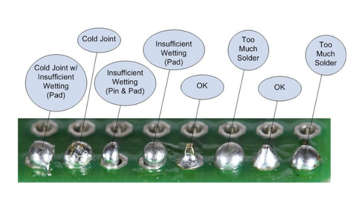
Solder joint inspection can identify solder joints that may compromise the final product.
What Happens When You Skip Solder Joint Inspection?
Communication with your PCB assembly supplier is key to understanding their soldering technology and inspection methods. Suppliers relying solely on manual visual inspection may pose challenges. Inadequate inspection can lead to undetected issues like faulty joints, causing problems during QA testing or even damaging ICs. Detection of flaws from reflow machines can be challenging, making manual inspection labor-intensive. Faulty joints may show intermittent issues, often remaining unnoticed until deployment, leading to frustration among technicians.
What Causes Bad Solder Joints?
Poor solder joints can arise from various factors. Frequently, the issue stems from the design and thickness of the stencil utilized in SMD reflow, which dictates the quantity of solder paste deposited on the PCB. When suppliers opt for thinner stencils, the solder holding the components can become worryingly sparse, potentially leading to imperfect connections.

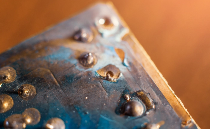
Mechanical stress may lead to bad solder joints.
Occasionally, problematic solder joints stem from the manufacturing process provided by the supplier. Deficient solder quality, improper techniques, and malfunctioning equipment can lead to unsatisfactory solder joints. Nonetheless, in certain instances, PCB designers may bear responsibility. For instance, boards designed with excessively small or large pads may exacerbate solder joint challenges.
How Do You Perform Solder Joint Inspection?
When prototyping via manual soldering, a magnifying glass aids in spotting solder irregularities. However, complexity increases with reflow soldering, especially for PCBs with BGA components. Solder joint inspection equipment is vital to detect issues like solder bridges or incomplete soldering.
Inspection machinery uses high-resolution cameras and X-ray technology to scan PCBs. Projected lights improve visibility, while sophisticated algorithms enable swift and precise inspections, especially in concealed areas like BGA pads.

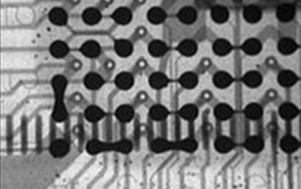
X-ray inspection is needed for BGA components.
While certain aspects of this issue may be beyond the influence of PCB designers, there are proactive steps you can take to mitigate the occurrence of poor solder joints. Utilize IPC-7531 component libraries integrated into your PCB design software to ensure compliance with industry standards.
Additionally, employing the appropriate PCB design and analysis software can proactively address potential solder joint issues before they manifest. Leveraging the advanced features of OrCAD PCB Designer allows you to establish best practices for prevention, detection, and correction, ultimately enhancing efficiency and driving cost savings across your organization.